▷ Practica 1 #PlcLab: Entradas y Salidas Digitales
Repositorio:
Materiales:
- PLC-LAB
- D1, D2 - Diodos Led
- R3, R4 Resistencias 100ohm
- R1, R2 Resistencias 1kohm
- 2 Interruptores
Requisitos previos:
Entradas y Salidas Digitales:
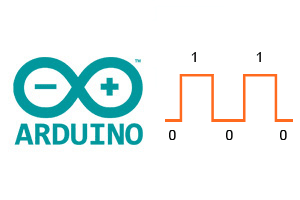
PLC-LAB cuenta con 12 I/O (Entradas/Salidas) digitales, localizadas en su lateral derecho. Una señal digital se caracteriza por contener dos valores posibles 0 y 1.
Eléctricamente en nuestro PLC-LAB un 0 digital representa 0[V] y un 1 digital representa 3.3[V]. Todos los pines de nuestro modulo trabajaran con esa lógica. Es importante tener en cuenta, que si nuestro modulo recibe mas que 3.3V en una de sus entradas, podría dañarse para siempre.
Para nuestro modulo tenemos las siguientes I/O disponibles:
Código:
This file contains bidirectional Unicode text that may be interpreted or compiled differently than what appears below. To review, open the file in an editor that reveals hidden Unicode characters.
Learn more about bidirectional Unicode characters
/* | |
Autor: Vidal Bazurto (avbazurt@espol.edu.ec) | |
GitHub: https://github.com/avbazurt/CURSO-PLC-LAB | |
Practica #1: Entradas y Salidas Digitales | |
*/ | |
//Entradas | |
#define INPUT_1 GPIO_NUM_23 | |
#define INPUT_2 GPIO_NUM_22 | |
//Salidas | |
#define LED_1 GPIO_NUM_23 | |
#define LED_2 GPIO_NUM_22 | |
//Constantes | |
bool status_input_1 = false; | |
bool status_input_2 = false; | |
void setup() { | |
/* | |
Definimos los pines para sus propositos | |
*/ | |
//Entradas | |
pinMode(INPUT_1,INPUT_PULLDOWN); | |
pinMode(INPUT_2,INPUT_PULLDOWN); | |
//Salidas | |
pinMode(LED_1,OUTPUT); | |
pinMode(LED_2,OUTPUT); | |
} | |
void loop() { | |
//Obtenemos la lectura de las entradas digitales | |
status_input_1 = digitalRead(status_input_1); | |
status_input_2 = digitalRead(status_input_2); | |
//Activamos o desactivamos las salidas | |
digitalWrite(LED_1,status_input_1); | |
digitalWrite(LED_2,status_input_2); | |
//Un pequeño delay | |
delay(500); | |
} |
Comments
Post a Comment